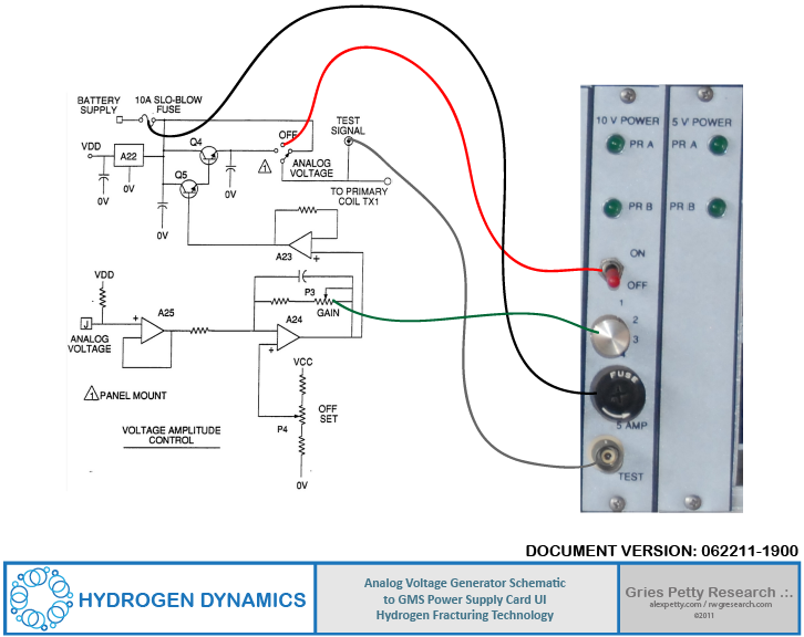
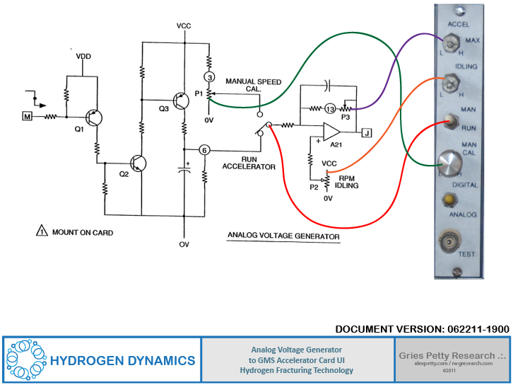
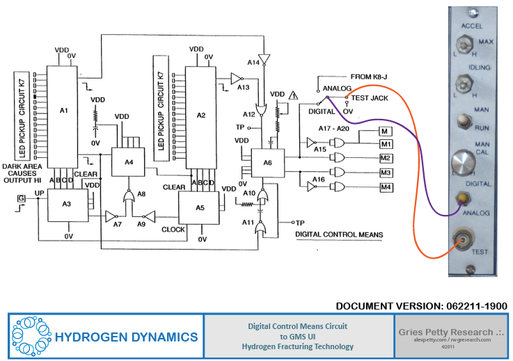
The various card modules of Meyer’s Hydrogen GMS system maps to the schematics in patent WO9207861 in the following manner.
Here are the cards installed in the GMS rack.
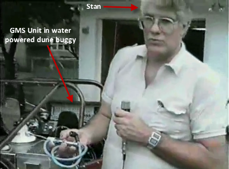
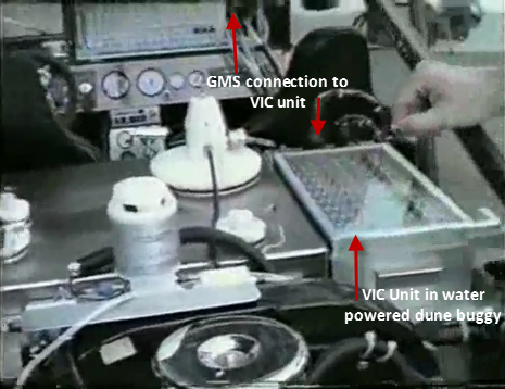
This was the control unit mounted in Meyer’s water-powered dune buggy. For a complete tour of the water-powered dune buggy, click this link:
http://alexpetty.com/2011/06/17/stan-meyer-tour-of-water-powered-dune-buggy-from-may-1992/
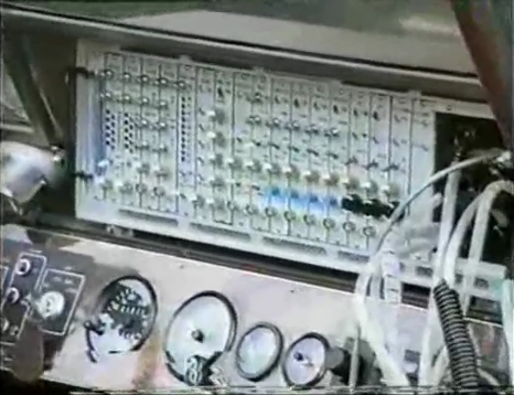
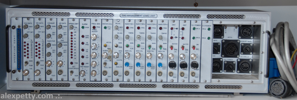
This GMS rack contains 18 module cards and a cable connection bay with eight ports. The card modules below are in order of the GMS rack from left to right:
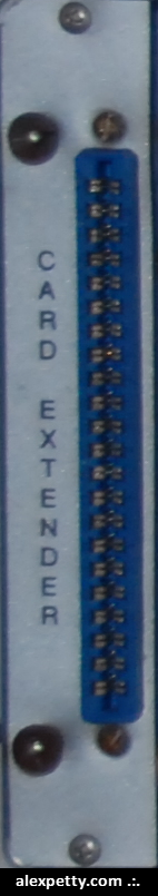
Card Extender Module
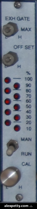
Exhaust Gate Module
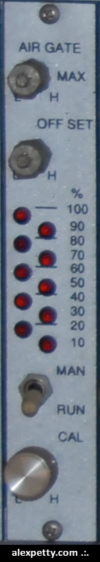
Air Gate Module
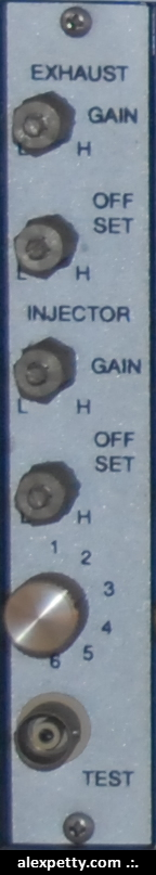
Exhaust Module
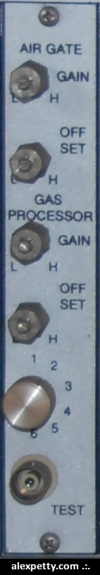
Air Gate 2 Module
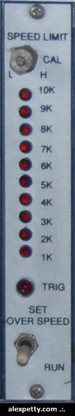
Speed Limit Module
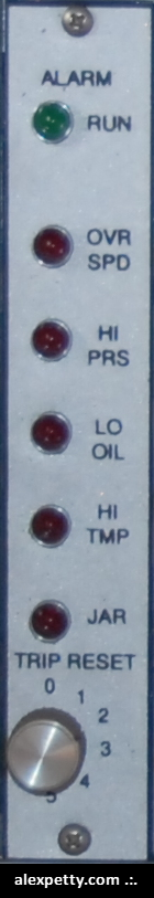
Alarm Module
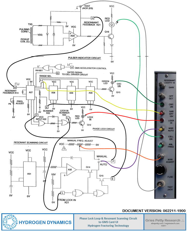
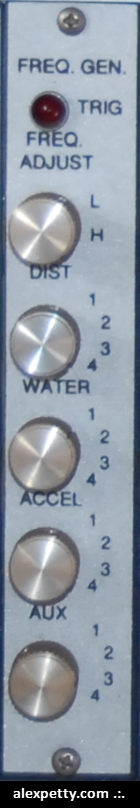
Frequency Generator Module
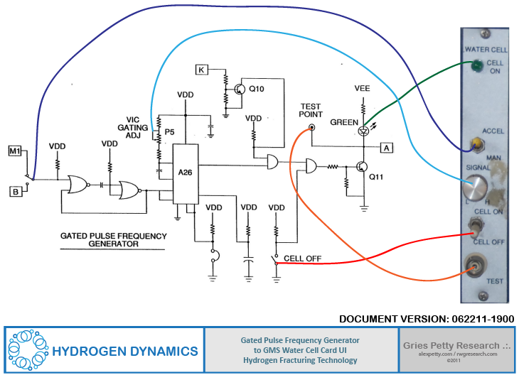
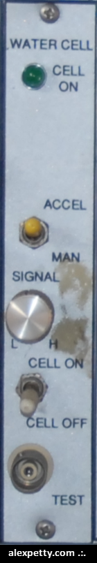
Water Cell Module
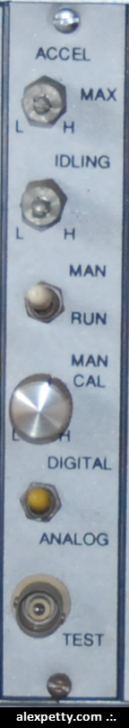
Accelerator Module
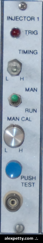
Injector 1 Module
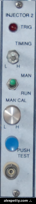
Injector 2 Module
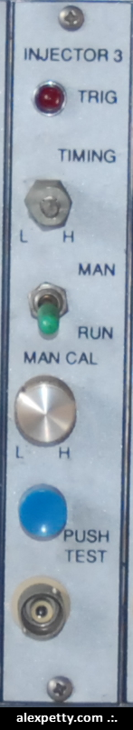
Injector 3 Module
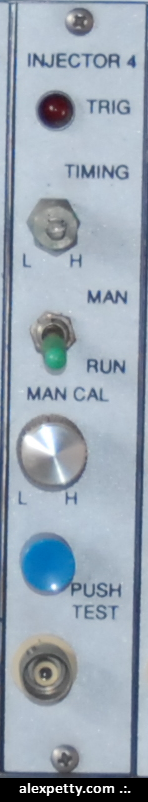
Injector 4 Module
Distributor 1 Module
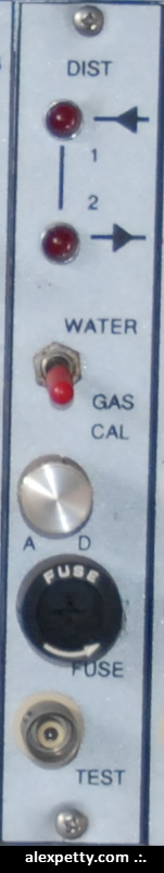
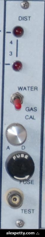
Distributor 2 Module
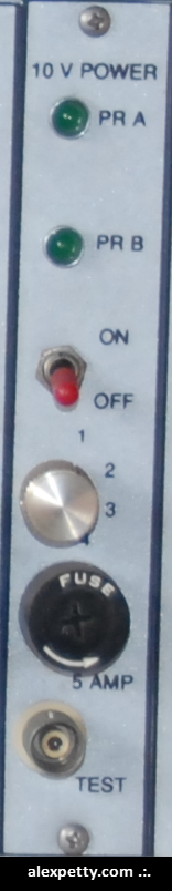
10V Power Module
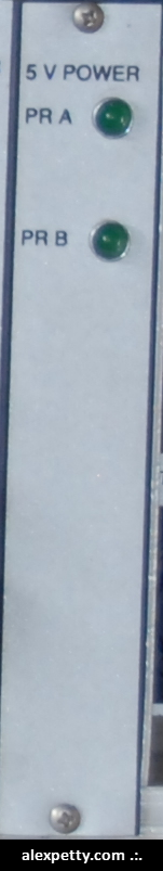
5V Power Module
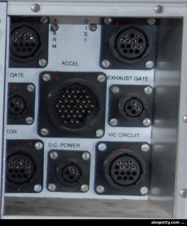
The cable connection bay contains eight ports:
1. Alarm (7 pins)
2. Dist (7 pins)
3. Gate (2 pins)
4. Accel (32 pins)
5. Exhaust Gate (2 pins)
6. TOR (8 pins)
7. DC Power (2 pins)
8. VIC Circuit (6 pins)
These ports are shown below:
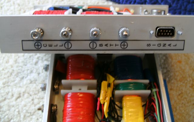
The GMS Unit was connected through the connection bay to the Voltage Intensifier Array Unit.
The VIC control unit was mounted on the back of the water-powered dune buggy as shown below.
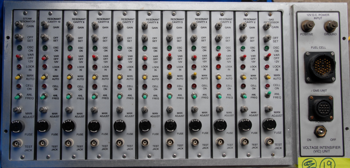
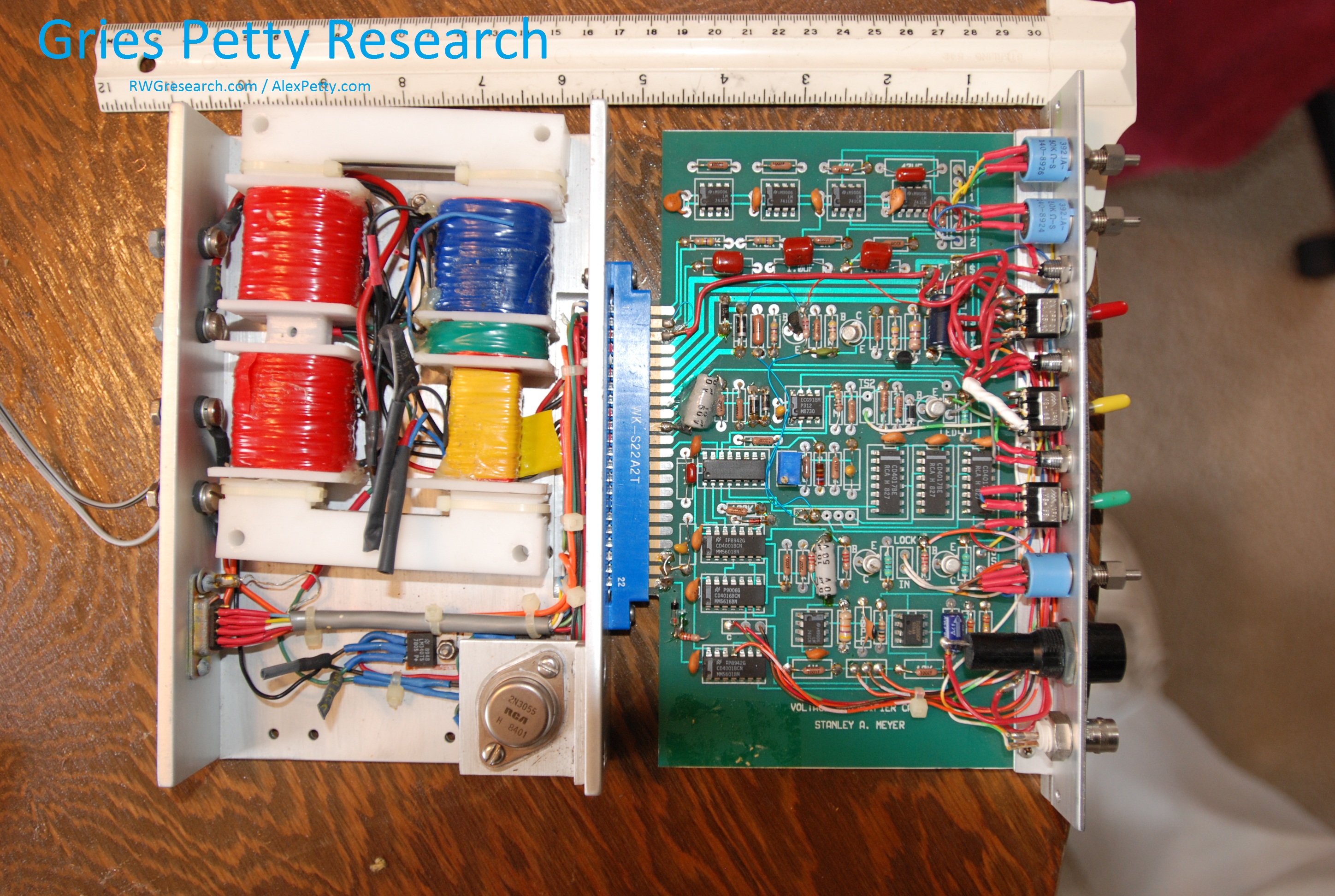
This rack contains eleven cards, 12VDC electrical terminals, two cable connection ports, and a power switch.
The card modules from left to right are:
1. Steam Resonator
2. Resonant Cavity 10
3. Resonant Cavity 9
4. Resonant Cavity 8
5. Resonant Cavity 7
6. Resonant Cavity 6
7. Resonant Cavity 5
8. Resonant Cavity 4
9. Resonant Cavity 3
10. Resonant Cavity 2
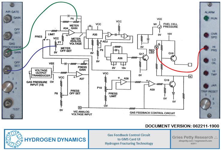
11. Gas Processor
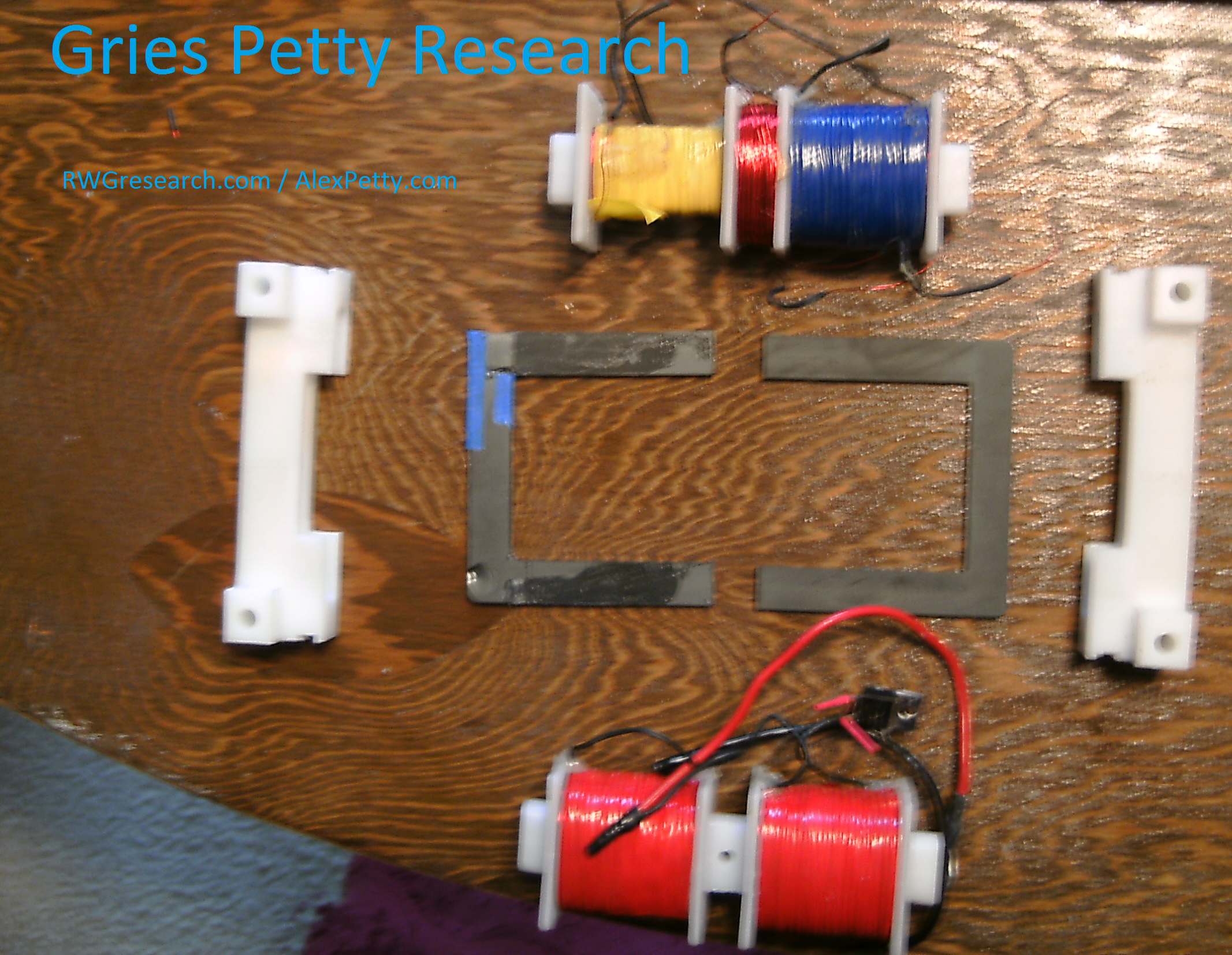
Each of these cards has the same user interfaces and are each connected to their own separate VIC (Voltage Intensifier Circuit).
DIGITAL CAMERA
.:.

Simple WFC Energization Circuit
Read Article
Stan Meyer Water as Fuel Lecture in Denver on May 1997
Read Article
Nice reference to the cards and wiring work
Dan