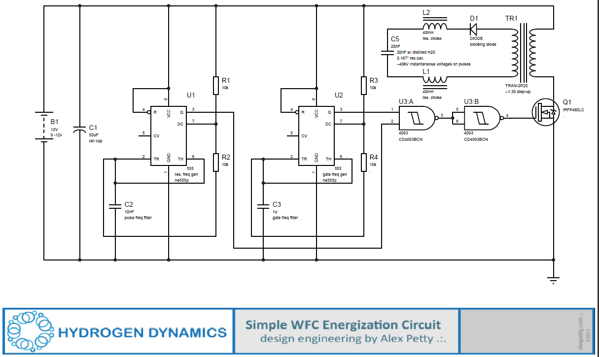
In response to those of you who want to build a cell but feel that you do not have enough knowledge in electronics to get started, I here present to you the simplest analog circuit that I have designed for the purpose of pulsing water fuel cells.
To adjust the frequency of your circuit into the resonant condition, switch out capacitor C2. You can use the following equation to get you into the ball park.
The resonant frequency for this case is given by:
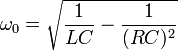
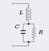
To use the equation, you will need to know the inductance of L1, the capacitance of C5 and the resistance your water poses to the charge that is trying to move between the plates of C5. Once you have calculated the resonant frequency, you then select a capacitor for C2 that will output square waves at this frequency. If you are unsure how to do this, just trial and error with a oscilloscope and watch for peak amplitudes on your pulses. (If you don’t have an oscilloscope, get one. It is an indispensable tool for this work.)
After you have “dialed in” to the resonant frequency for your circuit, you can add C3 (for the gate timing). This allows the water capacitor some time so it can discharge in order that it can then cycle the step charging process over and over again. The off-time provided by the gate also allows solitons to arise between the plates of C5.
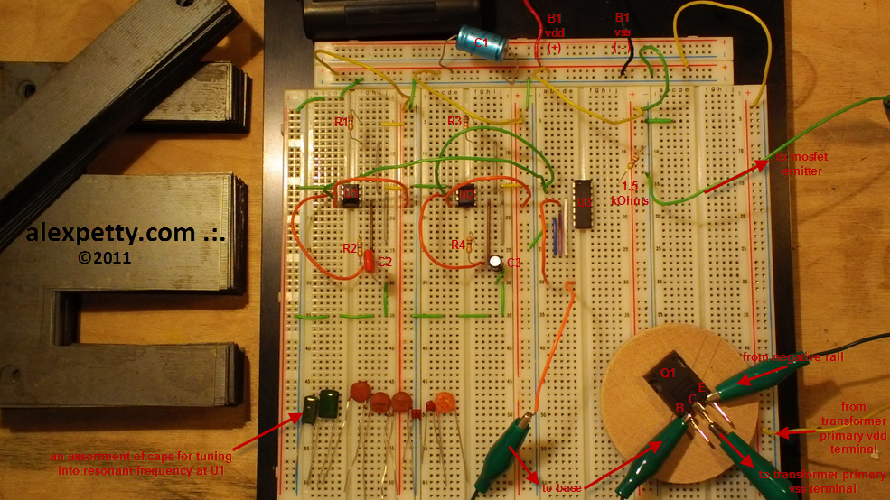
I am also including a photo of a breadboard on which I have implemented the above circuit. My hope is that this will give those of you who need it a better feel for mapping the schematic to actual physical connections.
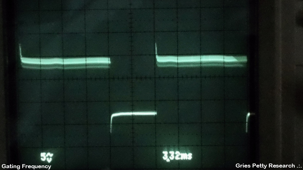
The view in the scope of the gating frequency at breadboard column 3 (the 3rd connection column from the left), at D15 (on U3) should look as given below:
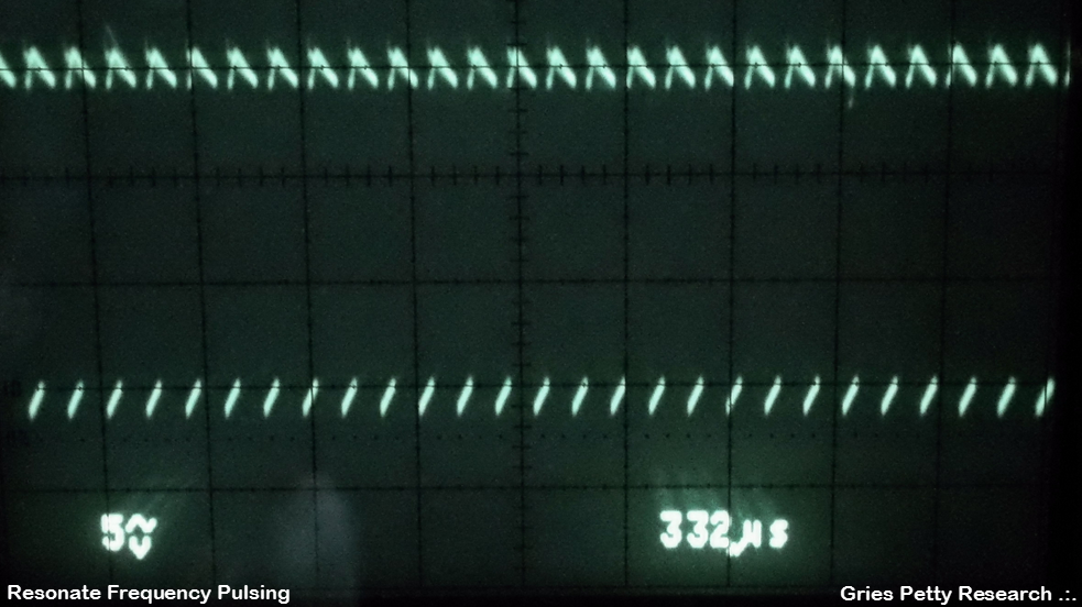
The view in the scope of the resonant frequency at breadboard column 3 (the 3rd connection column from the left), at D16 (on U3) should look as given below:
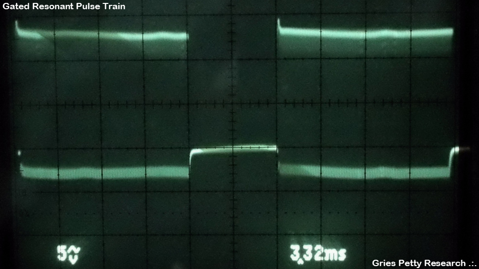
The view in the scope of the gated resonant frequency at breadboard column 3, D30 should look as given below:
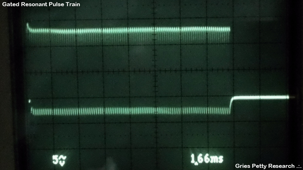
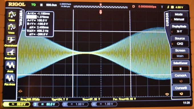
A higher time resolution scope view of the gated resonant frequency seen at Col.3, D30 should look as below:
If the VIC hardware is well constructed, and the given circuit is well tuned to that hardware, then the amplitude of the waveform you will see arise between L2 and C5 will show instantaneous voltages well above 40kV and higher. This is what facilitates the “electrical polarization process” effect.
This information I have just given you is the answer to often asked question about what is the capacitance (or some other parameter) of a Meyer cell. The fact is, the specific values of the components are less important then the knowledge that your real goal is to cause the cell to pulse in a resonant condition. By resonance, I am specifically referring to that condition which occurs when the capacitive reactance of C5 equals inductive reactance of L1 (and by extension, L2). This “resonant frequency” is dependent only on the characteristics of the electronic components in use, including the resistance value of your water dielectric.
Please feel free to share this design and use it however you wish as I am placing it into the public domain. If you re-post it, please include attribution to me and a link back to my blog. (Thank you for that.)
I hope you find this to be helpful.
.:.

Puharich Stage A
Read Article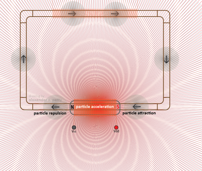
Meyer’s Gas Core Transformer
Read Article
Excelente Exelente Excelente! ya lo he probado inumeras veces, y me ha costado mucho entender y/o encontrar una explicacion tan simples como esa!
Excelente contribucion